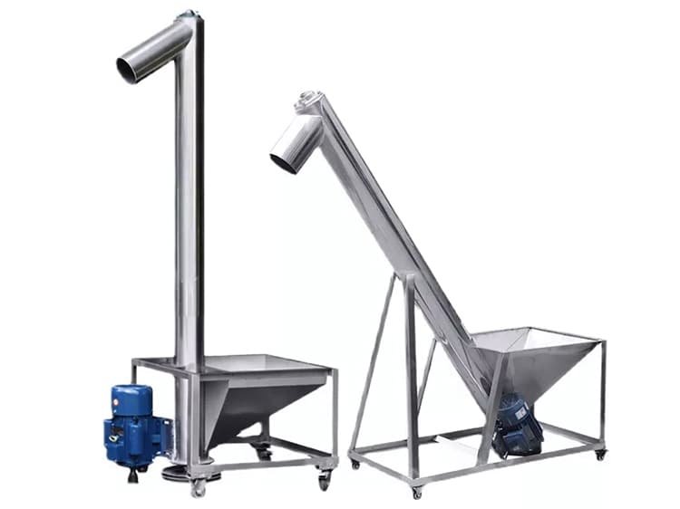
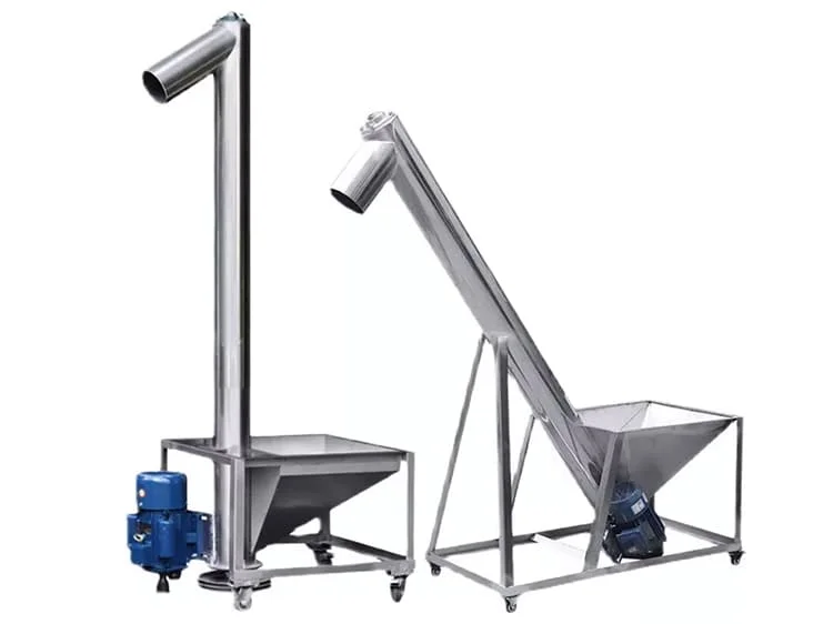
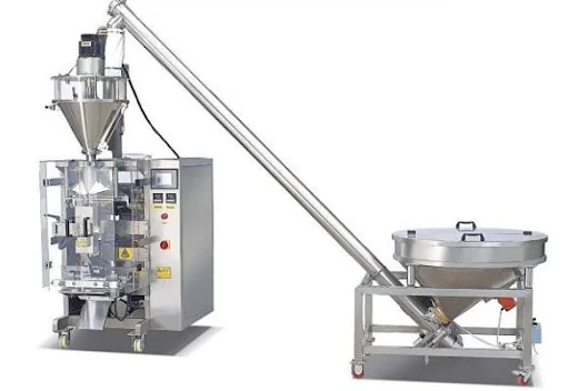
A screw conveyor is a conveying and transportation device driven by an electric motor, which rotates the blades to transport materials from one end to the other. It is widely used in industries such as food, construction materials, chemicals, environmental protection, and feed for efficient mixing and conveying. Today, I will take you through how a screw conveyor works. Before understanding its working principle, we need to first understand its components and their functions.

Components and functions of a screw conveyor
Drive motor: This is the power core of the screw conveyor. It provides power to the entire system, driving the spiral blades to rotate via belts or gears, thereby conveying the material.


Spiral blades: These are the primary components responsible for conveying the material. They come into direct contact with the material, rotating in a continuous loop to push the material from the front to the back. The shape and size of the blades may vary depending on the type of material being conveyed. The material is primarily steel, so it can cause damage to the material during transportation.
U-shaped trough or tubular casing: This is the channel for material transportation. It encloses the blades and material, forming a passageway that allows the material to move forward along the direction of the blade rotation without spilling out. A cover is typically added to the U-shaped trough for convenient material addition or maintenance.


Feed inlet and discharge outlet: These are straightforward. The feed inlet is where the material enters, typically located near the motor end of the screw conveyor (or at the required feed position); the discharge outlet is where the material is discharged from the screw conveyor, generally positioned at the required unloading location. The positions can be adjusted as needed.
Support bearings: These are the machine’s support points. They are installed at both ends or in the middle of the conveyor, securely supporting the rotating spiral shaft to ensure smooth and stable rotation without vibration. Without them, the shaft would rotate unstable, be prone to damage, and increase energy consumption.
The above are the main components of a screw conveyor and their functions. After understanding these components, if our equipment encounters issues, we can use this information to identify and address the corresponding problems for maintenance. Let’s now take a look at the working principle of the screw conveyor.
Working Principle of the Screw Conveyor
The working principle of the screw conveyor is straightforward, primarily relying on the continuously rotating screw blades inside:
Material Inlet: The material to be conveyed, such as powders, particles, or small pieces, is fed into the conveyor’s trough or pipeline through the inlet.
Rotating blade operation: When the motor starts, it drives the spiral shaft and the blades on it to rotate.
Material is pushed along: The rotating blades act like a continuously rotating “small shovel.” When the blades rotate in contact with the material, two main forces are generated: one is friction, which “adheres” the material to the blades; the other, more critical force is the axial thrust generated by the rotating surface of the blades. It is this axial thrust that continuously pushes the material along the trough or pipeline, from the feed opening to the discharge opening.
Continuous conveying: As long as the motor continues to run, the blades keep rotating, and the material is continuously pushed from one end to the other.
Material discharge: The material pushed to the discharge port falls out or is unloaded from there, completing the entire conveying process.
In simple terms, the motor drives the blades to rotate, and the blades act like screws, conveying the material trapped in the space formed between the blades and the trough wall from the feed end to the discharge end.

The above is the working principle of a screw conveyor.
Technical Specifications & Capacity Reference
Below is a typical performance data table for standard horizontal screw conveyors. Note: Actual capacity depends on material flowability and filling coefficients.
| Model (Diameter) | Max Speed (RPM) | Pitch (mm) | Filling Factor (ψ) | Capacity (m3/h) | Power (kW/5m) |
| LS200 | 60 – 75 | 200 | 0.33 | 12 – 15 | 1.5 – 2.2 |
| LS250 | 50 – 65 | 250 | 0.33 | 22 – 28 | 2.2 – 3.0 |
| LS315 | 45 – 60 | 315 | 0.33 | 45 – 52 | 4.0 – 5.5 |
| LS400 | 40 – 50 | 400 | 0.33 | 75 – 88 | 7.5 – 11.0 |
Engineering Calculation for Capacity
To determine the theoretical throughput (Q) for a horizontal screw conveyor, use the following engineering formula:
Parameter Definitions:
- D (m): Diameter of the screw flight.
- S (m): Screw pitch (standardly S = 0.8D to 1.0D).
- n (r/min): Rotational speed of the shaft.
- ψ: Filling factor (e.g., 0.15 for abrasive materials, 0.33 for free-flowing grain).
- ρ (t/m³): Bulk density of the material.
- C: Inclination coefficient (1.0 for horizontal; reduces as the angle increases).
Technical Troubleshooting & Maintenance
Data-driven analysis of common operational failures in industrial screw systems:
| Symptom | Probable Technical Cause | Solution |
| Material Blockage | Over-feeding or failure of the hanger bearing (material accumulation point). | Adjust feed rate; inspect hanger bearing clearance and lubrication. |
| Hanger Bearing Overheating | Friction between the shaft and bushing due to abrasive dust ingress. | Replace seals; use specialized wear-resistant alloy bushings. |
| Reduced Throughput | Screw flight wear leading to excessive clearance between blade and trough. | Restore blade diameter via hard-facing welding or replace screw sections. |
| Excessive Vibration | Shaft misalignment or unbalanced material loading in the trough. | Check coupling alignment and ensure the shaft is not bent. |
Conclusion:
The above covers the main components, functions, and working principle of a screw conveyor. As we can see, its structure is not complex; it relies on the coordination of the motor, blades, and trough to efficiently transport various materials from point A to point B. Due to its simplicity, reliability, high efficiency, and adaptability to various materials and environments, it is commonly used in food factories, construction sites, chemical plants, environmental projects, feed processing plants, and other such locations.
We are a manufacturer specializing in vibrating conveying equipment production lines, with over 30 years of experience. We can provide you with a variety of vibrating conveying solutions. Contact us now to receive the latest solutions and updates.
Email: info@sanyuantang.com
Phone: +86-18639095165
FAQs