Introduction
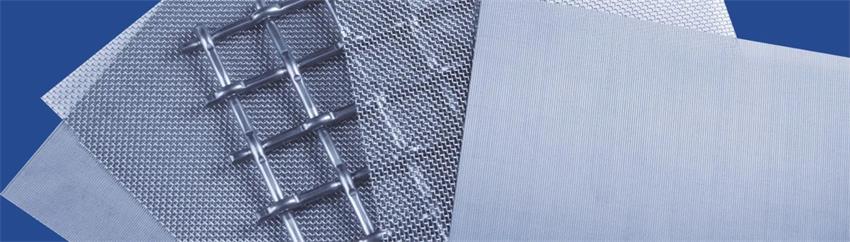
Selecting the correct wire mesh size chart reference is one of the most important factors in industrial powder processing and solid-liquid separation. The right mesh specification directly affects product quality, screening efficiency, and production capacity.
Improper mesh selection may result in material blinding, premature screen damage, excessive downtime, or an off-spec particle size distribution (PSD). This guide provides a standard wire mesh size chart, practical selection principles, and recommended mesh configurations for common industrial materials to help engineers optimize screening performance.
1. What Is Mesh Size? Definition and Mathematical Conversion
In the vibrating screen industry, mesh size is the primary parameter used to define screening fineness and particle classification.
Technical Definition
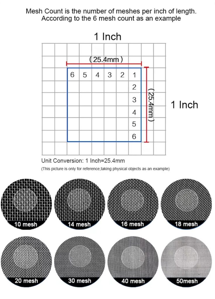
- Standard Definition: Mesh size refers to the number of openings per linear inch (25.4 mm) of the screen.
- Alternative Definition: Some regional standards define mesh as the total number of openings per square inch. Both definitions ultimately describe the geometric dimensions of the screen aperture.
Core Relationship
The relationship between mesh number and opening size follows an inverse proportion:
Higher Mesh Number → Smaller Aperture Size → Finer Particle Fraction
Understanding this relationship is fundamental when using any mesh size conversion or mesh to micron chart for industrial screening applications.
Mathematical Estimation Formula
When a complete wire mesh size chart is unavailable, engineers can quickly estimate screen aperture size using an empirical calculation based on the US Standard Sieve Series (ASTM E11).
According to the empirical relationship:
Mesh Count × Aperture Size (μm) ≈ 15,000
Example Calculation
For a 100-mesh screen:
- Aperture Size ≈ 15,000 ÷ 100
- Aperture Size ≈ 150 μm (0.15 mm)
This simplified calculation enables engineers and production personnel to rapidly estimate screening specifications during equipment selection, production planning, and on-site troubleshooting.
Variables Affecting Actual Aperture Size
The formula above provides only an approximate estimation.
Different manufacturers use different wire diameters, which directly influence the screen’s open area percentage (porosity). Consequently, screens with identical mesh counts may exhibit slight differences in their actual physical aperture size due to variations in weaving standards and wire thickness.
For applications requiring high classification accuracy, engineers should always verify the actual screen aperture size using manufacturer specifications or laboratory testing rather than relying solely on theoretical calculations.
2. Standard Wire Mesh Size Chart (Mesh to Micron/mm)
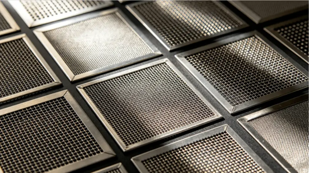
The following wire mesh size chart illustrates the relationship between standard mesh numbers and nominal aperture sizes based on industrial woven mesh specifications.
| Mesh | Aperture | Mesh | Aperture | Mesh | Aperture |
|---|---|---|---|---|---|
| 5 | 4.00 mm | 50 | 0.30 mm | 170 | 0.090 mm |
| 8 | 2.36 mm | 60 | 0.25 mm | 200 | 0.075 mm |
| 10 | 2.00 mm | 70 | 0.20 mm | 230 | 0.063 mm |
| 16 | 1.18 mm | 80 | 0.18 mm | 270 | 0.053 mm |
| 20 | 0.85 mm | 100 | 0.15 mm | 325 | 0.045 mm |
| 30 | 0.60 mm | 120 | 0.125 mm | 400 | 0.038 mm |
| 40 | 0.425 mm | 140 | 0.10 mm | 500 | 0.028 mm |
This mesh to micron chart serves as a practical engineering reference for selecting suitable screen aperture sizes across a wide range of industrial screening applications.
For more information on mesh sizes and thread counts, please read our article: Vibrating Screen Mesh Size and Pore Size Comparison Table
3. Empirical Mesh Configurations for Common Industrial Materials
Different industries require different industrial screening mesh specifications depending on material characteristics and production requirements.
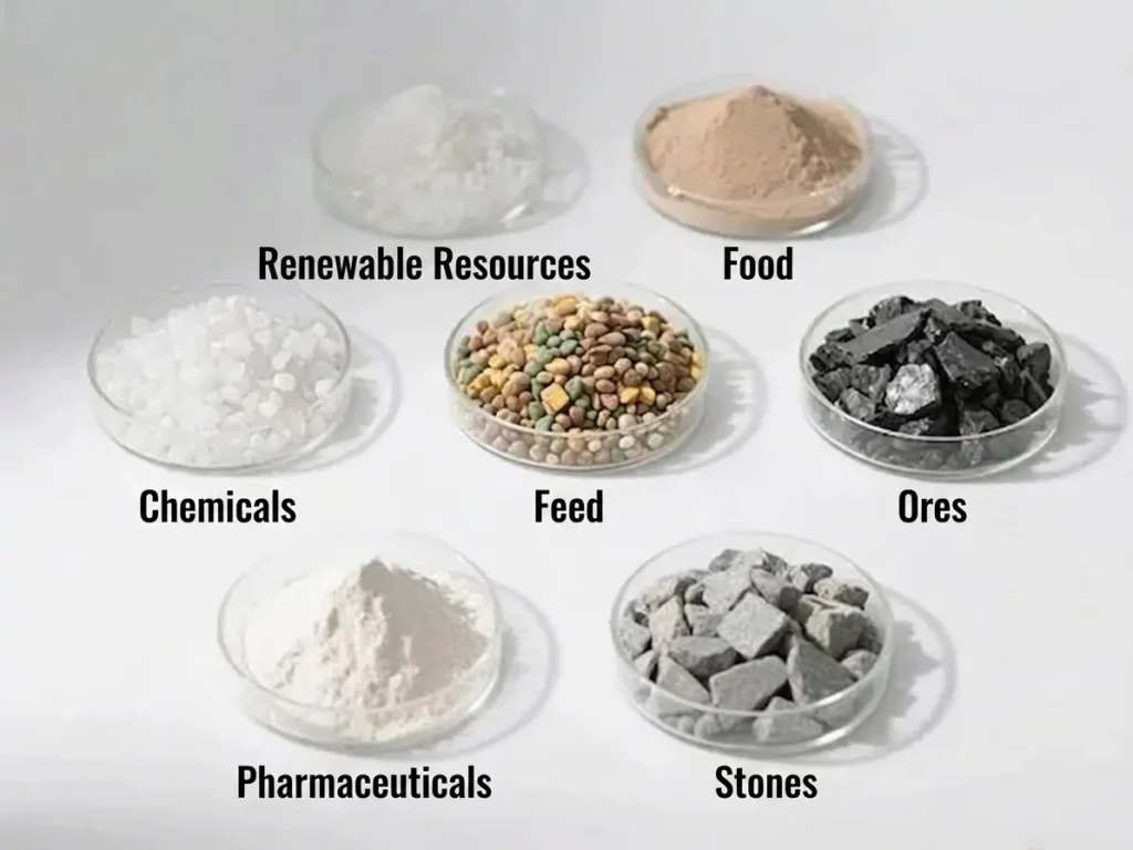
Quartz Sand (Silica)
Recommended Mesh: 10–140 Mesh
Lower mesh numbers are generally used for coarse scalping and dedusting, while finer mesh sizes are selected for accurate particle size classification.
Starch (Food & Industrial Grade)
Recommended Mesh: 80–120 Mesh
This range provides an ideal balance between product fineness and production throughput while maintaining stable screening efficiency.
Ternary Cathode Materials (Lithium Battery Production)
Recommended Mesh: 200–400 Mesh
Because lithium battery materials require extremely strict particle size distribution control, screening precision directly affects electrochemical performance.
Copper Powder (Metallurgy)
Recommended Mesh: 500 Mesh and Above
Fine powder metallurgy applications frequently require 600 mesh, 800 mesh, or even finer screening for sub-micron particle classification.
Operational Note
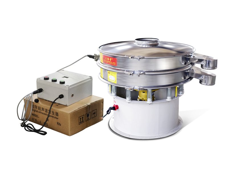
For ultra-fine powder screening above 200 mesh, conventional mechanical vibration often becomes less effective because of particle cohesion and electrostatic attraction.
Installing an ultrasonic anti-blinding system is highly recommended to maintain continuous screening efficiency and reduce mesh blockage.
4. Three Fundamental Principles for Mesh Selection
When selecting vibrating screen mesh size, engineers should follow these three principles in order of priority.
1. Follow Customer Specifications
Always comply with the engineering drawings and technical requirements provided by the end user. These documents should serve as the primary design standard.
2. Reference Industry Standards
Compare mesh selection with established practices in mature industries such as cement, abrasives, minerals, food processing, and milling applications.
3. Validate Through Material Testing
Laboratory sieve analysis remains the most scientific selection method.
Testing actual material samples provides accurate data regarding:
- Screening efficiency
- Mesh blinding tendency
- Throughput capacity
- Particle size distribution (PSD)
5. Standard Operating Procedure (SOP) for Vibrating Screen Mesh Selection
To minimize production errors, engineers should follow this standardized screening selection process.
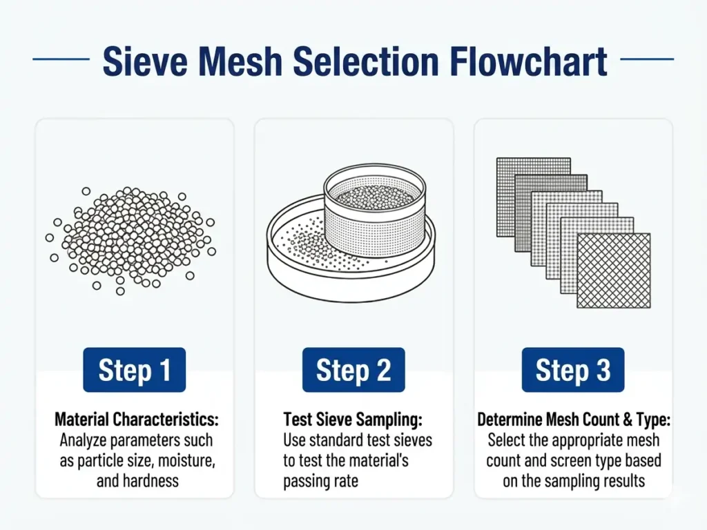
Step 1: Define Material Characteristics
Determine:
- Bulk density
- Moisture content
- Particle morphology
- Target particle size distribution (PSD)
Step 2: Preliminary Mesh Selection
Use the empirical material recommendations together with the wire mesh size chart above to determine an initial mesh range.
Step 3: Experimental Verification
Conduct screening tests to evaluate:
- Actual production yield
- Processing capacity
- Screening efficiency
- Potential mesh clogging
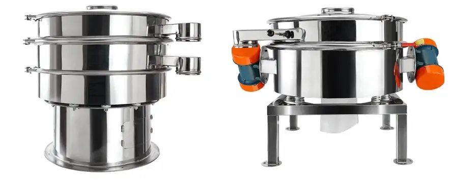
Step 4: Finalize Technical Specifications
Confirm:
- Wire diameter
- Mesh count
- Screen material
- Whether anti-blinding accessories such as bouncing balls or ultrasonic transducers are required
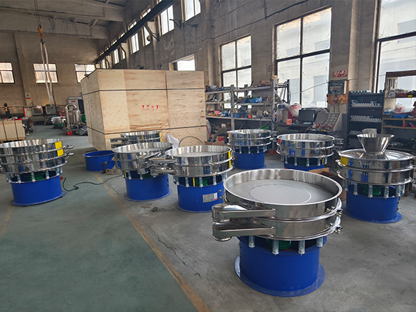
6. Sanyuantang Industrial Screening Solutions
Practical screening performance depends on verified testing rather than theoretical calculations alone.
Sanyuantang provides comprehensive application support for industrial screening projects.
Complimentary Material Laboratory Testing
Customers can send material samples to our testing laboratory.
Our application engineers perform professional sieve analysis and provide optimized mesh recommendations together with complete screening solutions based on empirical data.
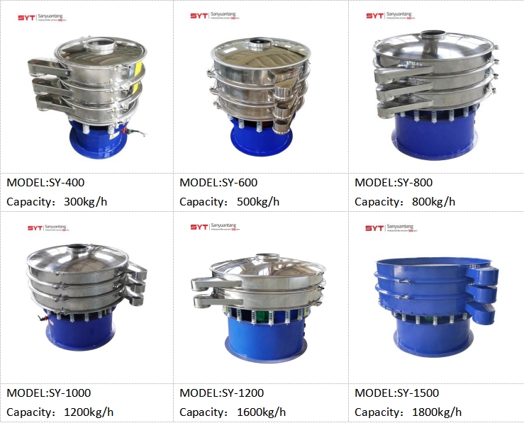
Full Inventory Specifications
We maintain continuous inventory covering standard screen sizes from 60 mesh to 500 mesh, ensuring fast delivery for most industrial applications.
Customized Ultra-Fine Screening Solutions
For applications requiring particle classification beyond 500 mesh, Sanyuantang develops customized composite mesh structures that maximize service life while maintaining precise aperture control and high production throughput.

Conclusion
Selecting the correct wire mesh size chart is the foundation of efficient industrial screening. Understanding the relationship between mesh count, aperture size, and particle classification enables engineers to improve product quality, maximize throughput, and reduce operating costs.
By combining standard mesh size conversion references, laboratory testing, and practical engineering experience, manufacturers can achieve more stable screening performance and longer screen service life.
Whether processing silica sand, starch, battery materials, metal powders, or other industrial bulk solids, choosing the appropriate vibrating screen mesh size remains the key to building a reliable and efficient screening system.
Email: info@sanyuantang.com
Phone: +86-18639095165